

Download Spec Sheet436.5 KB
Download 3D PDF573.98 KB
Download STP21.22 KB
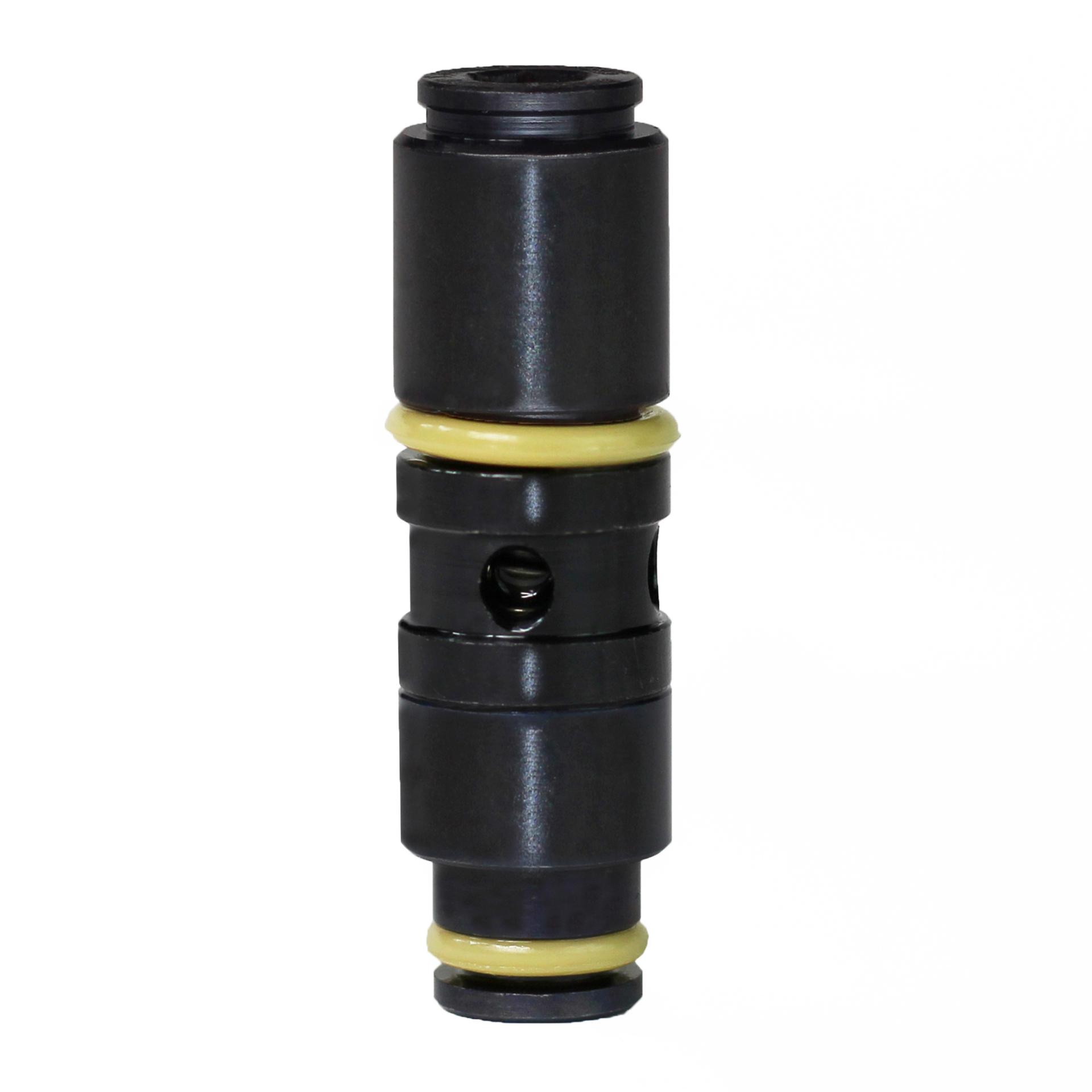
Product Image
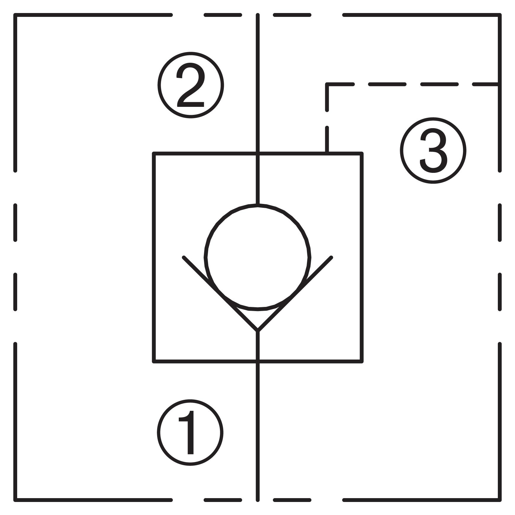
Schematic
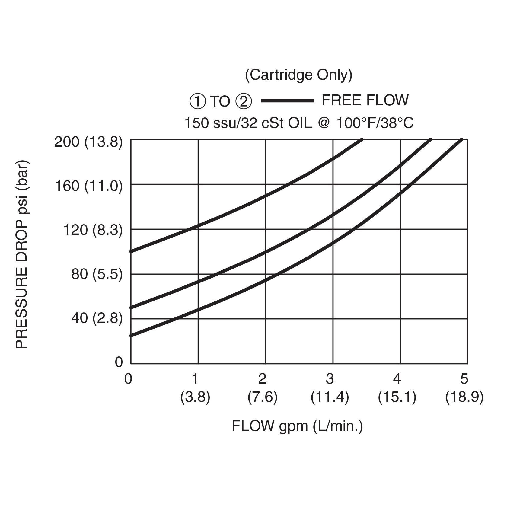
Pressure Drop vs Flow
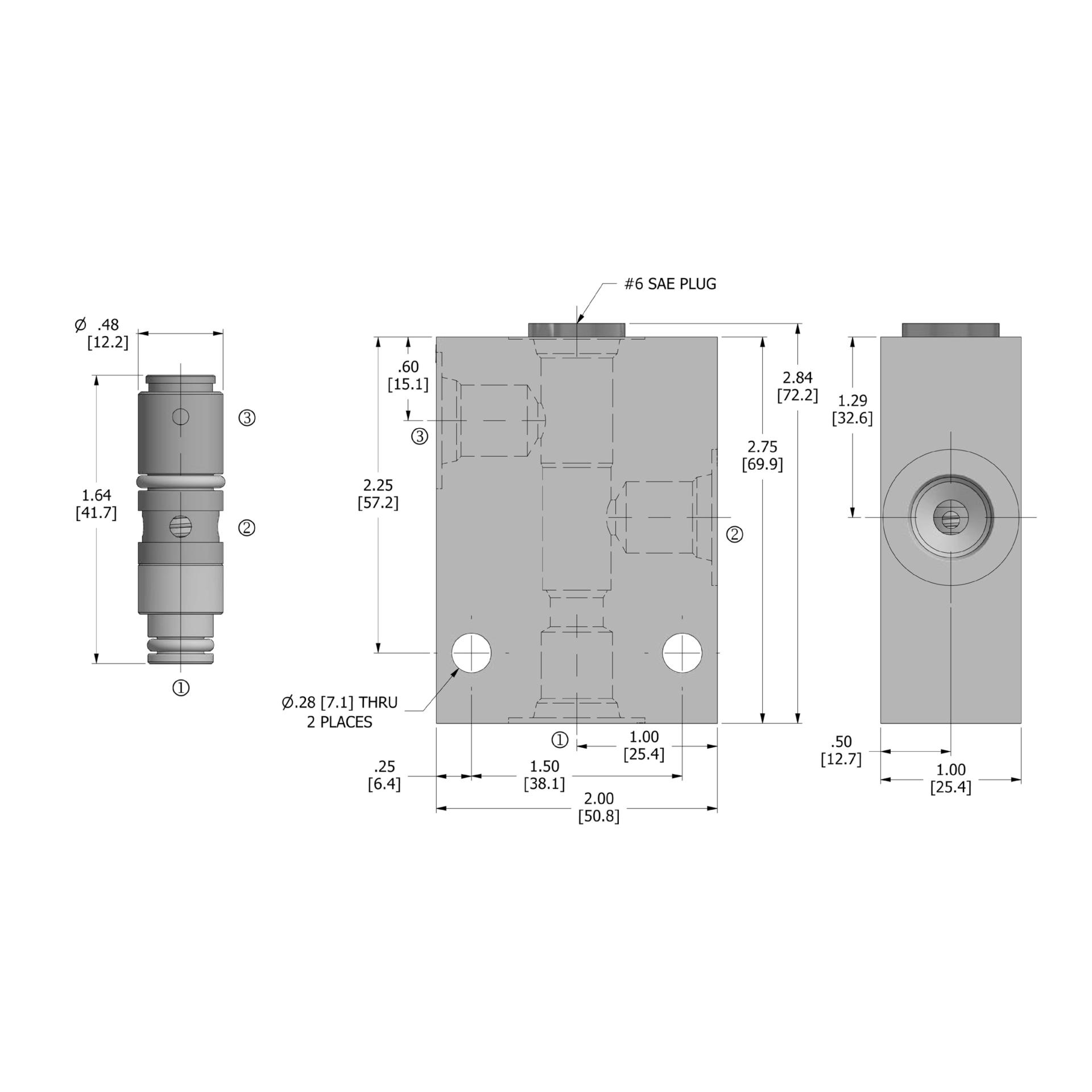
Dimensions
How to Order

Description
A cartridge valve designed to allow free flow in one direction, while preventing flow in the opposite direction. Free flow can be blocked by reaching the required pilot pressure. This valve is commonly used as a load-holding or blocking valve.
Operation
Pressure at ➀ overcomes the spring-bias ball and allows free flow to ➁. Flow in the opposite direction, from ➁ to ➀, is blocked by the ball. When the required pilot pressure is achieved at ➂, the ball is held closed to block flow between ➀ and ➁. The pilot piston area to ball seat area ratio is 3 to 1.
Features and Benefits
- Slip in style.
- Compact size.
Specifications
Max Operating Pressure (psi)
3000
Flow gpm
3.0
Flow lpm
11.4
Cavity
Valve Style
Ball
- Operating Pressure: 3000 PSI (207 Bar)
- Flow:
- See PRESSURE DROP VS. FLOW graph.
- Nominal Flow 3 GPM (11.4 L/min).
- Internal Leakage: 5 drops/min. max. at 3000 psi (207 bar).
- Crack Pressure:
- 25 PSI (1.7 Bar)
- 50 PSI (3.4 Bar)
- 100 PSI (6.9 Bar)
- Pilot Ratio: 3 to 1
- Temperature: -30°F to +250°F (-35°C to +120°C)
- Recommended Filtration:
- Critical Application – ISO 17/15/13
- Non-Critical Application – ISO 20/18/14
- Fluids: Mineral-based fluids. For other fluid compatibility, consult factory.
- Installation/Removal Tool: Consult factory
- In-Line Body Material: Anodized 6061T6 aluminum alloy rated at 3000 PSI (207 Bar).

